
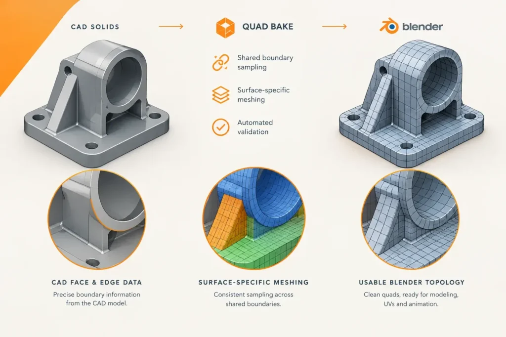

The developer of Seamless CAD has detailed Quad Bake, a new approach to converting CAD solids into meshes intended for continued work in Blender. Rather than simply passing OpenCASCADE’s display tessellation through, the add-on uses the solid’s B-rep faces and edges to build a quad-oriented mesh with UVs, seams and sharp-edge data. That targets a familiar handoff problem: tessellation adequate for display or STL output can be awkward to edit, subdivide or unwrap.
The central design choice is to divide each CAD edge once and share those sampled points between adjoining faces. The developer says this avoids relying on a later vertex weld to close face boundaries. It also ties the meshing process to known CAD topology instead of trying to infer surface groups from an existing triangle mesh. The implementation splits work between a C++ kernel stage, which establishes edge divisions, and Python code that meshes faces according to their surface type. I would treat shared edge sampling as the key integrity decision: both adjoining faces reuse the points established on the edge, rather than depending on a later positional weld. That keeps the adjoining faces aligned along their shared boundaries, but does not by itself rule out internal defects elsewhere in the mesh. If the handoff requires a closed manifold, check for open boundary edges and non-manifold edges or vertices; reject or repair the mesh if any remain.
Surface-aware meshing, with fallbacks
Quad Bake selects different methods for different geometry. Cylindrical sides can become regular quad bands when their opposing rim divisions match; cones retain unequal rim counts to avoid excessively narrow quads near the apex, so some triangles can remain. Four-sided curved faces use Coons-patch interpolation, while planar faces with holes use a quad border and constrained Delaunay triangulation for the remaining area. Unsupported cases also fall back to triangulation, so “quad bake” should be read as quad-oriented output, not a guarantee that every polygon will be a quad.
To keep the mesh useful beyond simple curved faces, the developer describes propagating edge-division constraints between neighboring faces and adding an optional Uniform Density mode. That mode subdivides straight cylinder and extrusion sides and carries finer spacing across connected edges. For large planar regions around small holes, the grid is capped at 20,000 points; the developer says the tool then grades from the finer hole boundary toward the coarser grid in staged transitions. These choices address competing needs—consistent edge flow and manageable mesh size—but they also mean local topology depends on the model and settings.
I would not maximize mesh density by default: finer spacing can preserve detail around holes, while the reported 20,000-point cap and staged transitions reflect the need to keep planar regions manageable. For a handoff, inspect a representative part at the intended density, especially around holes and transitions; choose finer spacing only if the coarser result misses required detail and the resulting mesh remains manageable.
Triangles created by some face methods are paired into quads using a maximum-weight matching process, with shape quality informing the pairing. The article also describes per-face reports that show which meshing method was used, UV islands based on CAD faces, seams assigned to CAD edges and sharpness derived from CAD face continuity. A “Leave Out of Bake” option can omit selected features from the baked shape while retaining the parametric history, which may help produce a lighter mesh without simplifying the editable CAD model itself.
Testing and availability
The developer reports automated checks for watertightness, duplicate unshared vertices, volume deviation and outward orientation across several sample shapes and tolerances, including STEP-exported and re-imported geometry. Those are useful checks for geometric integrity, but they do not establish that every resulting mesh has clean, deformation-ready topology. I would treat the per-face report as just as important as the quad conversion: it identifies where fallback methods were used, including triangulation. Inference: fallback triangles can interrupt regular quad flow around holes, which may make subdivision less even or complicate loop-based edits. Before using a baked part for subdivision, painting or further modeling, inspect those regions and their topology on the actual component, especially around holes and transitions in density. Reject the mesh for that handoff if the fallback regions disrupt the required quad flow or produce unwanted results under the intended subdivision.
The announcement confirms that Quad Bake has been implemented, but it does not specify an add-on build number or say which downloadable release contains it. Confirm with the developer which release includes Quad Bake. On a representative part, check the mesh density around its smallest relevant features and holes, and verify that the chosen Quad Tol keeps chordal error within the tolerance required for the handoff. The baked mesh remains separate from the editable B-rep; it is a route into Blender’s polygon workflow, not a promise of uniformly all-quad topology.
Sources
- Bringing CAD shapes into Blender with “clean quads” — How Seamless CAD’s Quad Bake works — ひなたふぐ / note
- Seamless CAD — Parametric Modeling in Blender — Hugu’s Works / Superhive
- Seamless CAD documentation — Hugu’s Works